Ask us about
test equipment solutions for your industry
What is Radiated Immunity?
Radiated immunity testing, also known as radiated susceptibility testing, is one of the four primary EMC tests methods, along with radiated emissions, conducted immunity, and conducted emissions. This test evaluates an electronic device’s ability to resist the electromagnetic interference (EMI) that emanates from surrounding electronic devices.
EMC radiated immunity testing tells manufacturers and consumers whether a DUT can handle the stray EMI that comes from any electronic device in the vicinity. This interference comes from common sources, such as phones, computers, and power lines.
Failure within an electronic system can result in weakened performance, data loss, or complete system failure. When applied to MIL and AERO applications, this can be extremely costly. A particularly costly example would be if the inner workings of a rocket were to malfunction, causing it to blow up. Keep reading to learn more about radiated immunity testing setups and standards.
Radiated Immunity Test Setups
Radiated immunity test setups can vary drastically depending on the device being tested, the standards the DUT must meet, etc. That being said, there are common pieces of radiated immunity test equipment. Below we will go over the steps for setting up a radiated immunity test procedure and some of the equipment that will be used, as well as a diagram for visuals.
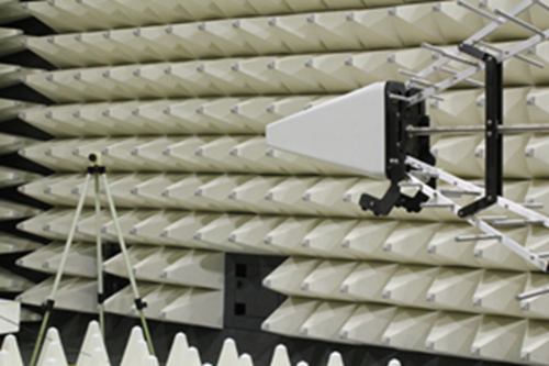
- Before you can begin the radiated immunity testing, you should set up an E-field probe inside your anechoic chamber.
- An anechoic chamber is a room that prevents EMI radiation from reflecting off the walls, ensuring a higher level of accuracy when reading measurements.
The E-field probe records the intensity of the RF fields inside the anechoic chamber, providing real-time feedback that testers can observe through a field monitor attached directly to the probe. It makes sure the equipment is emitting/measuring the correct set of frequencies and field levels before actually evaluating the DUT.

- Once the correct measurements are put in place, you can then set the DUT on a turntable in an anechoic chamber.
- The turntable is designed to spin the DUT around in the center of the room so the radiation can be fired at the DUT from the same distance throughout the testing process.
- Outside of the chamber, a signal generator creates the radiofrequency waves that the power amplifier then amplifies to match the strength of the EMI that would be found in real-world situations.

- The dual directional coupler (DDC) provides a feedback measurement loop to the RF power meter and sensors to measure the VSWR and power going to the antenna. The EMC antenna then transmits the known RF field into the anechoic chamber.
Below is a diagram of a typical radiated immunity test setup.

Additionally, testers can also use HIRF (High-Intensity Radiated Field) testing to perform radiated immunity testing. This type of testing sends strong radio frequency (RF) signals at the DUT to see if that impacts the device’s performance. This type of testing typically complies with aerospace regulatory agencies such as the FAA (Federal Aviation Administration) and EASA (European Aviation Safety Agency). To learn more this form of testing and its relation to radiated susceptibility, please visit our solutions page on HIRF testing.
Radiated Immunity Test Standards
Test standards typically dictate how these radiated immunity tests are performed. Different industries have different requirements for their wide variety of equipment. Below we will touch on a few of the major radiated immunity test standards.
- IEC 61000-4-3 – This standard applies to radiated immunity requirements applied to electrical and electronic equipment.

- IEC 61000-4-21 – Tests EMI immunity for electric and electronic equipment while in reverberation chambers. This standard would not be applicable to test setups using an anechoic chamber, but is commonly used for radiated susceptibility tests.
- CISPR 16-2-3 – Focuses on radiated disturbance measurements within a 9kHz – 18GHz frequency range.
- CISPR 16-2-4 – Specifies the measurement of EMI immunity within the frequency range of 9kHz – 18GHz.
- MIL-STD-461G RS101 – This standard applies to equipment and subsystem enclosures (including cable interferences) tested within a frequency range of 30Hz – 100kHz.
- MIL-STD-461G RS103 – Used to verify a DUT’s ability to withstand electric fields. Frequency range varies depending on applicability.
- 2MHz – 30MHz is for Army, Navy, and optional for other military branches.
- 30MHz – 18GHz is for all branches.
-
18GHz – 40GHz is optional for all branches.
- MIL-STD-461G RS105 – Tests requirements related to equipment and subsystem enclosures that are outside of shielded platforms and facilities.
- RTCA/DO-160 Section 20 – Tests for radiated and conducted susceptibility (immunity) when exposed to RF radiated fields over a 100MHz – 18GHz frequency range.
Radiated Immunity Test Equipment
ATEC has a vast catalog of EMC test equipment from leading manufacturers such as Amplifier Research and Keysight. We rent a plethora of test and measurement equipment that help test labs perform radiated immunity pre-compliance and full compliance testing . Below are some notable examples of equipment that can aid you in your next radiated immunity test:
 These four pieces of equipment are useful for a standard radiated immunity test setup. Additional pieces of equipment such as dual directional couplers can also be found on our website. Contact us today to learn more!


