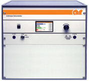
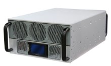
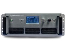
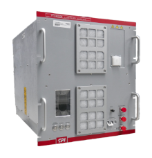
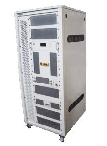
What Is an RF Amplifier?


RF power amplifiers are commonly used to drive antennas, injection devices and other loads in EMC immunity testing, wireless communications, radar, aerospace and defense applications.
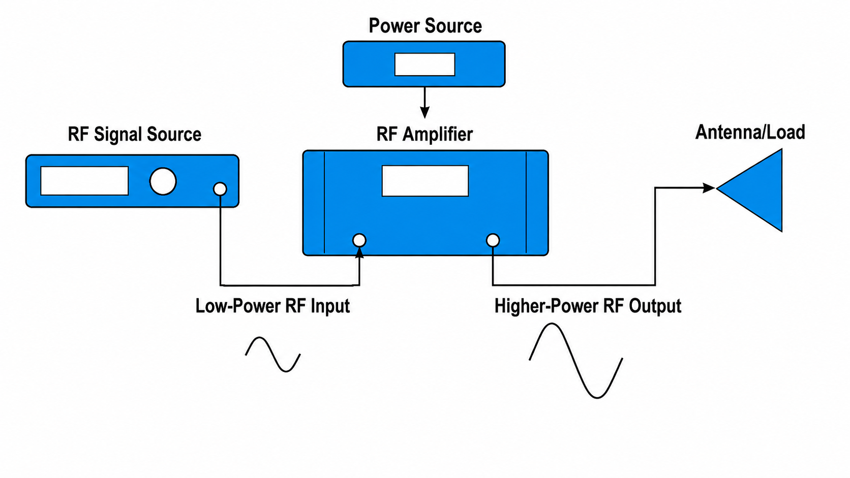
How Does an RF Amplifier Work?
Types of RF Power Amplifiers
Pulse Amplifier
Solid-State RF Amplifier
CW Amplifier (Continuous Wave Amplifier)
TWT Amplifier (Traveling Wave Tube Amplifier)
Solid-state amplifiers and TWT amplifiers each have advantages depending on frequency, output power, bandwidth, efficiency and application requirements. Compare SSPA vs. TWTA amplifiers to understand which technology is better suited for your test setup.
Amplifier Categories by Properties
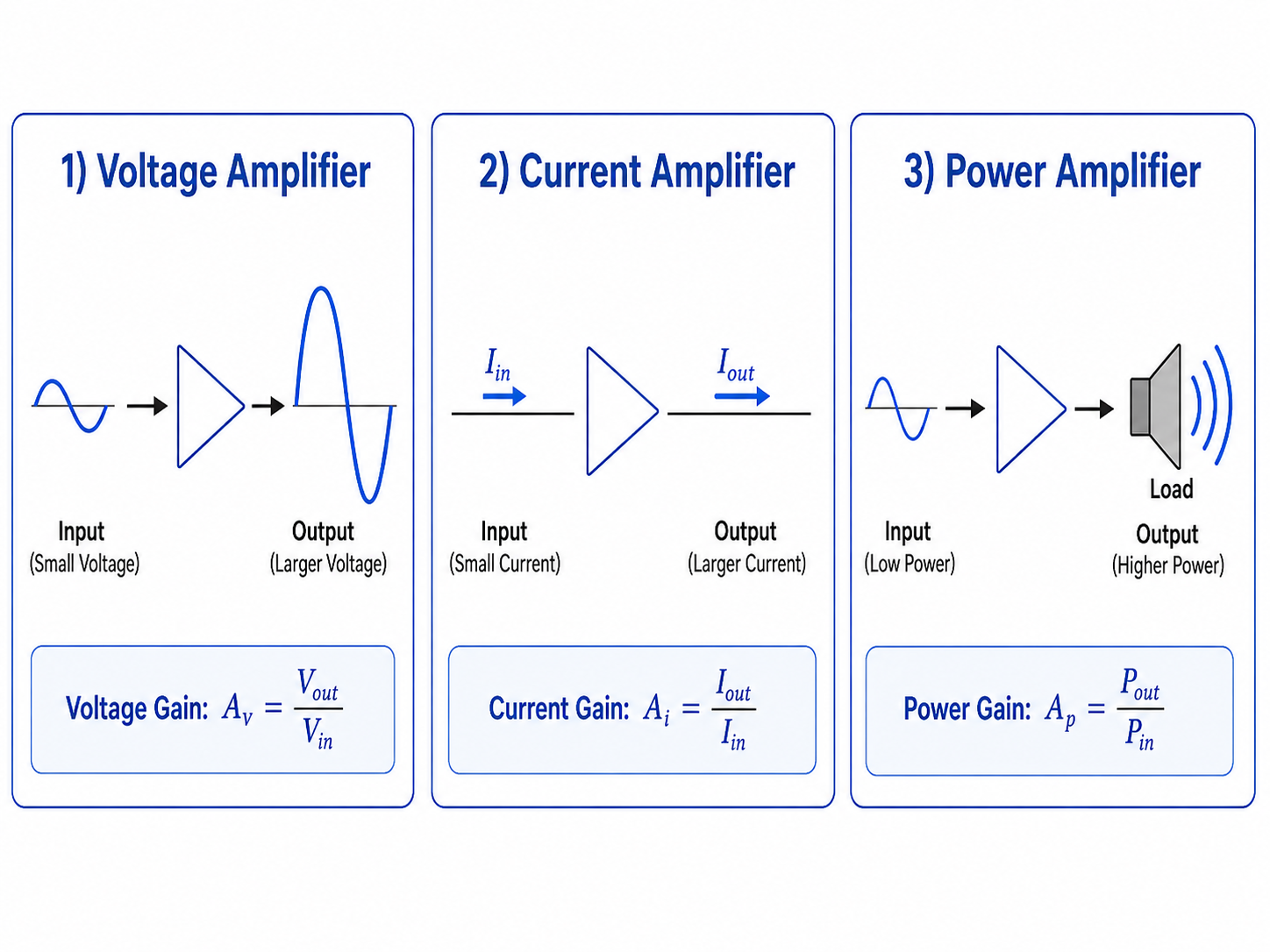
Amplifier Categories by Signals
1. RF Amplifiers
Radio frequency power amplifiers are designed to convert a low-power RF signal to a higher-power signal. RF amplifiers are available across a wide range of frequencies, from kilohertz frequencies through microwave and millimeter-wave ranges depending on amplifier design.
2. Audio-Frequency Amplifiers
AF Amplifiers amplify audio signals within the audible frequency range of 20 Hz to 20 kHz. Audio-frequency amplifiers are commonly used in sound systems for applications such as concert venues, stadiums and consumer audio equipment.
3. Intermediate Frequency Amplifiers
Intermediate-frequency (IF) amplifiers amplify signals that have been converted from their original RF frequency to a fixed intermediate frequency inside a receiver or transmitter. Using a fixed IF makes it easier to provide consistent gain, filter unwanted noise and signals, and improve selectivity before further processing. IF amplifiers are commonly used in radio receivers and other communications systems.
4. Broadband Amplifiers
Broadband RF amplifiers provide amplification across a wide frequency range, allowing a single amplifier to support multiple RF and test applications without frequent test equipment and setup changes.
Other amplifier types include video, operational, buffer and DC amplifiers. These are designed on a different scale for different electronic applications when compared to RF power amplifiers.
RF Amplifier Applications
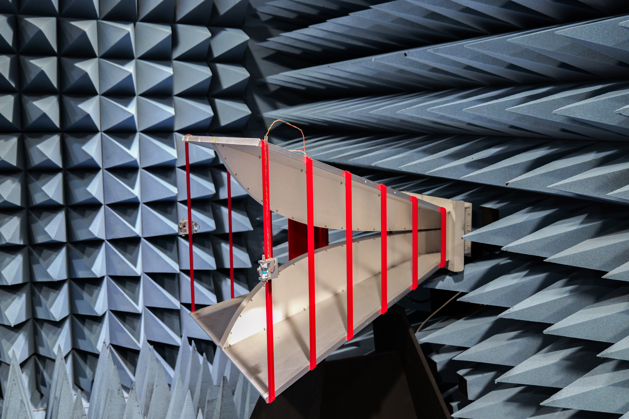
EMC Immunity Testing
- Radiated Immunity
- Conducted Immunity
- TEM/GTEM Cells
- Bulk Current Injection
- Reverberation Chamber
Aerospace, Defense and Radar
- Pulse Radar Systems
- Electronic Warfare (EW and E3 Testing)
- Avionics
- Space and Satellite Systems
- Military Communications
Wireless and Communications
- Wireless Device Testing
- Telecom Systems
- Satellite Communications
- RF Component Testing
- Transmitter and Receiver Development
RF Amplifier Characteristics and Specifications
-
Frequency Range: The range of frequencies over which the amplifier meets its specified performance, including output power, gain and other applicable specifications.
-
Rated Output Power: The RF power the amplifier can deliver specified as CW or Peak Pulse Power and as P1dB or Saturated Power.
-
Gain: The ratio between RF Output and Input Power, expressed in decibels (dB).
-
Gain Flatness: The variation of the amplifier's gain across the operational frequency range, typically expressed as ± dB.
-
Linearity and Compression: An amplifier produces a proportional output only within its linear operating range. The 1dB compression point, or P1dB, identifies where gain begins to compress noticeably.
-
Harmonics and Distortion: Unwanted frequency components produced by amplifier nonlinearity that may affect signal quality or EMC test field uniformity.
-
VSWR and Mismatch Tolerance: The amplifier's ability to operate safely when power is reflected back toward the output by an antenna, injection device, cable or improperly matched load.
-
Pulse Specifications: For pulse amplifiers, important specifications include peak power, pulse width, duty cycle, rise time, pulse repetition frequency (PRF).
Amplifier Classes
RF amplifier classes describe how an amplifier’s active device conducts during each signal cycle. This is referred to as the conduction angle of the amplifier. The amplifier class influences important characteristics such as linearity, efficiency, distortion and heat generation. Class A provides the highest linearity, while Class AB, B and C trade off linearity for improved efficiency.
| Amplifier Class | Conduction Angle | Linearity | Efficiency | Typical RF Use |
|---|---|---|---|---|
| Class A | 360° | Highest | Low | Highly linear RF amplification |
| Class AB | 180°–360° | High | Moderate | Linear RF power amplifiers |
| Class B | 180° | Moderate | Higher | Push-pull RF stages |
| Class C | <180° | Low | High | Tuned RF transmitters |
In general, increasing conduction angle improves linearity but reduces efficiency. Classes with lower conduction angles can improve efficiency at the expense of increased distortion.
RF Amplifiers for EMC Immunity Testing
RF power amplifiers are an essential part of many EMC immunity and susceptibility test systems. The amplifier increases the RF signal from a signal generator to the power level required to drive an antenna, bulk current injection probe, coupling device or other RF load.
Depending on the product and industry, RF amplifiers may be used to support testing to standards such as:
- IEC 61000-4-3 - Radiated RF immunity testing for electrical and electronic equipment.
- MIL-STD-461 RS103 - Radiated susceptibility testing for military equipment and subsystems.
- RTCA DO-160 Section 20 - Conducted and radiated RF susceptibility testing for airborne equipment.
- ISO 11452 - Automotive component immunity testing for electrical disturbances from narrowband electromagnetic energy.
Learn more about EMC testing methods and equipment used for immunity and susceptibility testing.
How to Choose an RF Amplifier
Every RF amplifier application has a required frequency range and output power level. Selecting the right amplifier also depends on the load it must drive and how that load behaves across frequency. VSWR tolerance, reflected-power protection and amplifier foldback can be important when operating into antennas or other mismatched loads.
Amplifier gain, linearity and compression performance also matter. Some applications require operation near P1dB without excessive waveform compression, while others prioritize efficiency or maximum available power. These trade-offs can influence whether a Class A, Class AB, solid-state or TWT amplifier is better suited for the application.
Explore RF Power Amplifiers
-compressed_25.png?width=220)