
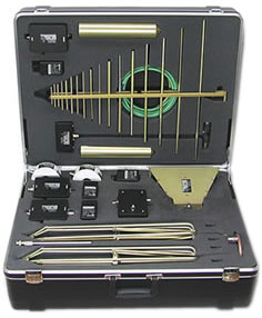
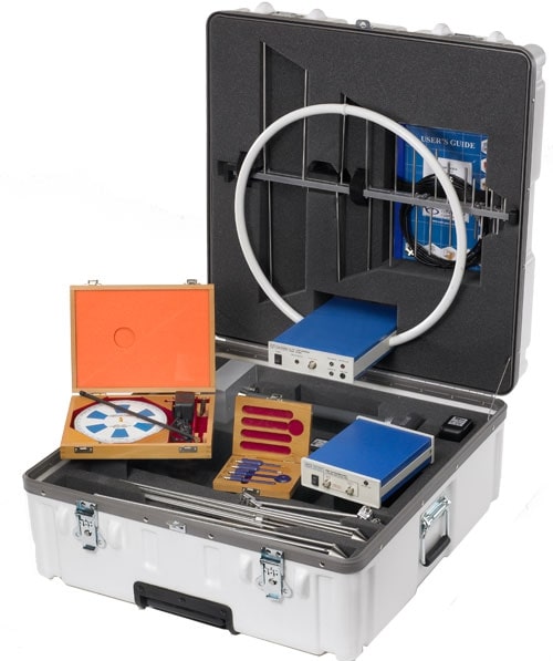
AH Systems AK-18G EMC Antenna & Probe Kit
- Frequency Range: 20Hz - 18GHz
- Active Loop Antenna
- Gain: 33dB

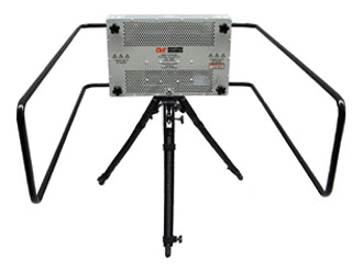
Amplifier Research ATE10K100M E-field Generator
- Frequency Range: 10kHz - 100MHz
- Power Handling: 500W (max)
- Field Intensity: 350V/m (A), 200V/m (B) w/ 500W input

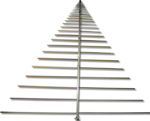
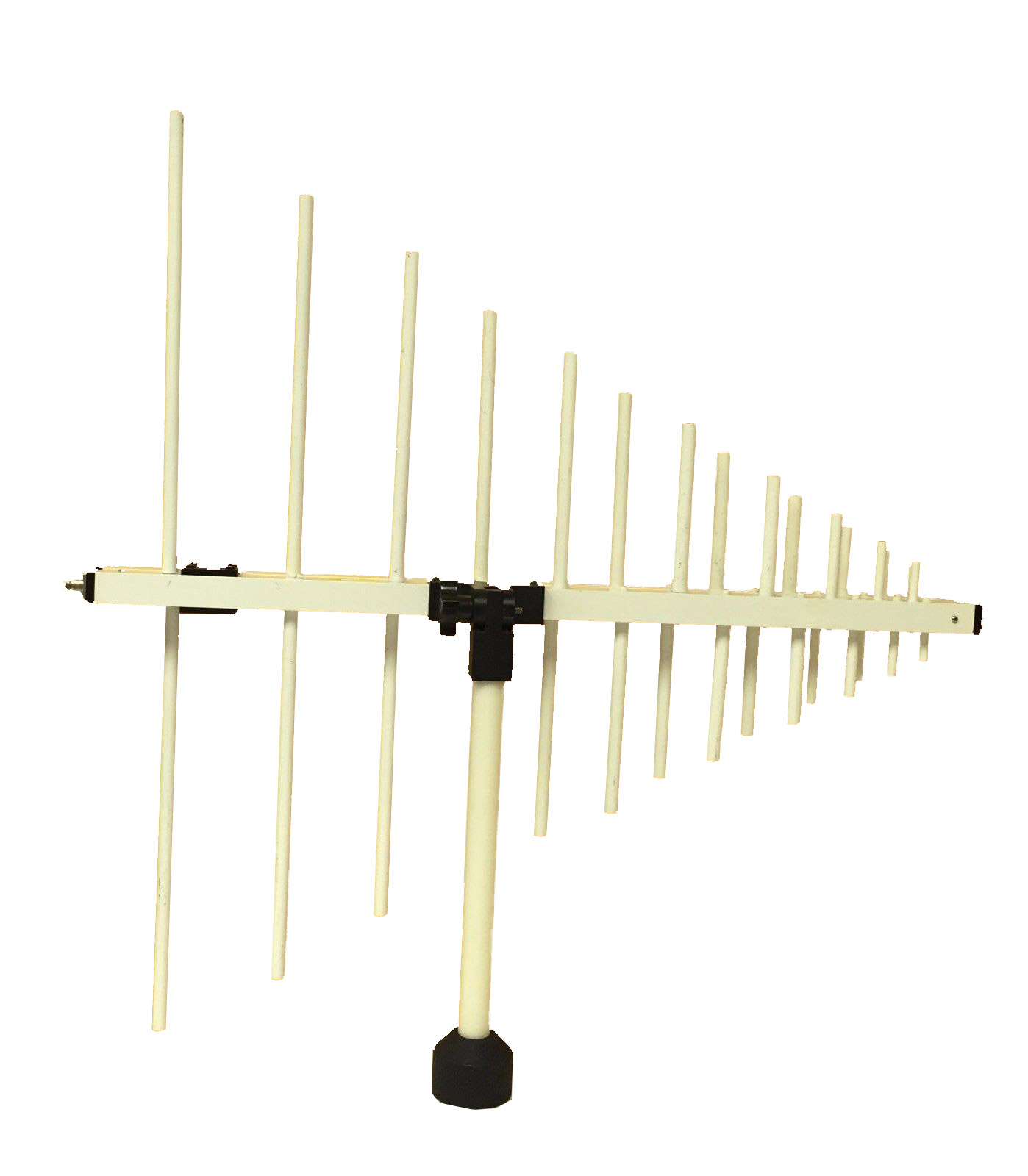
AH Systems SAS-517 Log Periodic Antenna | 80 MHz - 4 GHz
- Frequency range of 80 MHz to 4000 MHz
- Receive and transmit
- Individually calibrated (1, 3, and 10 Meter calibration included, horizontal polarization)
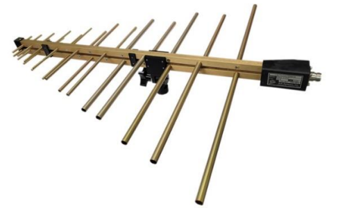
AH Systems SAS-510-2 Log Periodic Antenna | 290 – 2000 MHz
- Frequency range of 290 MHz to 2000 MHz
- Receive and transmit
- Individually calibrated
Electro-Metrics EM-6950 Log Periodic Antenna | 200 MHz - 1 GHz
- Wide frequency coverage
- High sensitivity
- Flat frequency response

ETS-Lindgren EMCO 3146A Log Periodic Antenna
- 300MHz - 1GHz
- 50 ohms
- 1kW Max. Cont. Power

Com-Power ACL-6000 Biconilogical Antenna
- Frequency Range: 30MHz - 6GHz
- Power Handling: ~200W (Cont.)
- Isotropic Gain: -20... 7dBi

TDK RF Solutions EFG-03 E-Field Generator
- Frequency Range: 10kHz – 100MHz
- Power Handling: 3.5kW
- Field Intensity: >500V/m
TDK RF Solutions EFG-02 Electric/Magnetic Field Generator
- Frequency Range: 10kHz - 100MHz
- Power Handling: 3.5kW
- Field Strength: <500V/m RMS
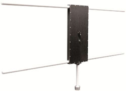
IFI EFG-3B E-Field Generating Antenna 2000 Watts
- Frequency Range: 10kHz - 220MHz
- Power Handling: 2kW
- Connector: Type C, Female
IFI EFG-3 E-Field Generating Antenna 1000 Watts
- Frequency Range: 10kHz - 220MHz
- Power Handling: 1kW (CW)
- Connector: N-Type, female

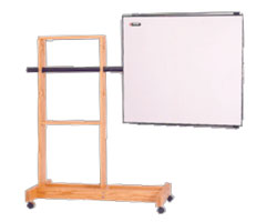
ETS-Lindgren 3170 Intell-I-Tune Antenna
- Frequency Range: 30 – 200MHz
- Power Handling: 2500W
- Field Intensity: 200V/m @ 1m
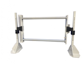
ETS-Lindgren 3107B Parallel Element E-Field Generator
- Frequency Range: 10kHz - 30MHz
- Power Handling: 1kW
- Field Intensity: 100V/m
Amplifier Research ATE10K25M-1 E-Field Generator
- Frequency Range: 10kHz - 25MHz
- Power Handling: 2kW (max)
- Field Intensity: 200V/m (at 2.5kW input)
Amplifier Research ATE10K30MA E-Field Generator Antenna
- Frequency Range: 10kHz - 30MHz
- Power Handling: 2kW
- Field Intensity: ≤100V/m
Com-Power ANK-910L EMC Test Antenna Kit with Active Loop Antenna
- Frequency Range: 1MHz - 1.5GHz
- High Gain Preamplifier
- Near Field Probe Kit
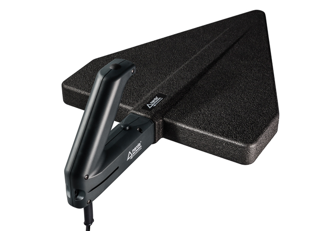
Narda IDA Directional Log Periodic Antenna 3, 3100/13 | 400 MHz - 6 GHz
- High measurement sensitivity
- Directional characteristic largely frequency-independent
- Mechanically robust

Keysight 11956A Log Periodic Antenna | 200 MHz – 1 GHz
- Frequency range of 200 MHz to 1 GHz
- Max continuous power of 1 kW
- Connector type N female


ETS Lindgren 3148B Log-Periodic Dipole Array
- Frequency: 200 MHz - 2 GHz
- Continuous Power: 1 kW
- Gain: 5 dB

Amplifier Research ATR80M6G Log Periodic Antenna
- Frequency: 80 – 6000 MHz
- Typical Gain: 6 dBi
- VSWR: 2.0:1 typical, 3.0:1 maximum

Advanced Antennas LPD-70M1G Log Periodic Antenna
- Frequency range: 70MHz - 1GHz
- Max. continuous power: 1kW
- Gain: 60dBm
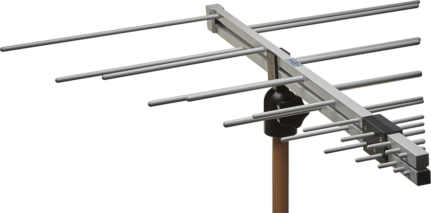
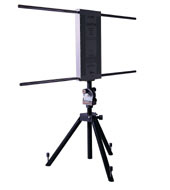
PMM LP-04 Log Periodic Antenna | 200 MHz - 6 GHz
- 200 MHz to 6 GHz frequency range
- Excellent antenna factor
- Tripod adapter for easy vertical-horizontal polarization change

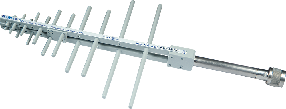
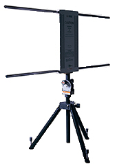
PMM LP-03 Log Periodic Antenna | 0.8 - 6 GHz
- 0.8 to 6 GHz frequency range
- Excellent antenna factor
- Tripod adapter for easy vertical-horizontal polarization change
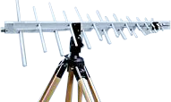
PMM LP-02 200 MHz - 3 GHz Log Periodic Antenna | 6 dB Gain
- 200 MHz to 3 GHz frequency range
- Excellent Antenna factor
- Tripod adapter for easy vertical - horizontal polarization change
ARA LPD-3500 Log Periodic Dipole Antenna
- MHz: 300 - 5000
- dBi: 4.5
- Back(dB): 18