Multipaction Testing
Multipaction testing is used to evaluate how RF components respond to high-frequency signals in vacuum environments. This testing is critical for aerospace applications, where RF-induced breakdowns can cause performance degradation or failure. People sometimes refer to the phenomenon as the multipactor effect, a term common in European aerospace standards.
Understanding the Multipactor Effect
Under the right RF conditions, free electrons in a vacuum can strike surfaces with enough force to release additional electrons. This can trigger a cascading avalanche known as multipaction, leading to RF noise, arcing, and component damage.
Multipaction most often affects space-based systems and components such as:
- Waveguides and coaxial lines
- Filters, diplexers, and couplers
- Antennas and connectors
- Microwave and RF passive components
Types of Multipaction
- Single-Surface: Occurs on dielectric surfaces where electrons build locally.
- Two-Surface: Involves electrons bouncing between two metal surfaces in close proximity.
When Does Multipaction Occur?
- Vacuum environment with low pressure
- Presence of free electrons (from radiation or electron sources)
- RF power and frequency tuned to cause resonance
- Electron travel time aligns with half-period multiples of the RF waveform
Multipaction Testing Methods
- Global Testing: Evaluates complete systems for signs of breakdown such as harmonics and power loss.
- Local Testing: Focuses on individual components to determine threshold conditions for multipaction onset.
Test Equipment Categories
ATEC rents high-performance equipment to support multipaction testing, including:
- Pulse Amplifiers
- RF Signal Generators
- RF Power Meters & Sensors
- Spectrum Analyzers
- Preamplifiers
- Data Loggers
Multipaction Test Setup
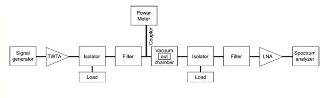
This block diagram shows a typical multipaction test setup, including a signal generator, pulsed amplifier, directional couplers, vacuum chamber, and downstream RF analysis equipment.
How to Check Conditions for Multipaction Testing
- Test set-up calibrated prior to testing
- Multipaction standard used to verify the test set-up
- Power level ramped from 1600 Watts peak, 315 Watts average to 3000 Watts peak, 600 Watts average, in 200 Watts intervals with 5 minutes dwell at each level. 30 minutes dwell at maximum power of 3000 Watts peak, 600 Watts average
- Forward, reflected and output powers continuously monitored and recorded
- Third harmonic signals at input and output continuously monitored and recorded
- Current probes (Pico ammeters) placed at all ports through the vent holes to detect possible anomalies
- Several thermocouples placed on DUT and base plate to continuously monitor and record the temperature
- Thermal vacuum chamber pressure continuously monitored
- Visual inspection after multipaction testing using a microscope
Vacuum Chamber Configuration
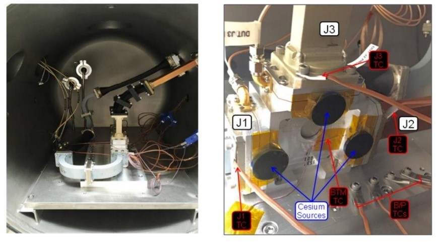
Pictured above is a physical multipaction test environment, featuring Cs-137 electron sources, temperature sensors, and current probes inside a thermal vacuum chamber simulating orbital RF exposure.
Test Parameters
| Parameter | Setting | Notes |
|---|---|---|
| Frequency | 7.0 GHz | Primary RF carrier |
| Power | 3000 W peak | 600 W average |
| Pulse Width | 100 µs | 5% duty factor |
| Pressure | <1.0e-5 Torr | Vacuum environment |
| Temperature | -10 to +23 °C | Test chamber conditions |
| Electron Source | Cs–137 | 3 sources, 10 µCi each |
| Sample Rate | 50 kHz | Signal monitoring rate |
| Detection Methods | Return loss, harmonics, picoammeters | Used to detect anomalies and thresholds |
| Samples Tested | 20 | Number of components evaluated |
Related Testing
ATEC also provides Radiated Immunity Testing services, which evaluate how devices withstand external RF interference in compliance with EMC regulations.
Simulation Software Tools
- CST Studio Suite: 3D EM simulation and RF modeling
- Spark3D: RF vacuum breakdown prediction software
- Fest3D: Passive RF component simulation
Contact ATEC
ATEC provides rental equipment and expert support for multipaction and RF breakdown testing. Contact us today to find the right equipment for your mission-critical project.