Ask us about
test equipment solutions for your industry
How to Use a Laser Shaft Alignment Tool
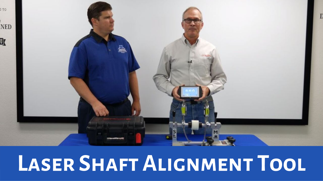
This video demonstrates how to do a simple horizontal laser shaft alignment using two shafts featuring Steve Gordon, sales manager at Vibralign. Click here to learn more about the Vibralign Fixturlaser EVO Laser Shaft Alignment Tool.
We’re going to show the operation of a laser alignment using a Vibralign Fixturlaser EVO Laser Shaft Alignment Tool. These are the various sensor units one is marked "S" for the stationary side, and one is marked "M" for the movable side, typically the electric motor. So, we're going to take the "S" sensor which is for the stationary piece. The "M" as I said earlier, typically goes on the motor or the movable element and again we'll just quickly attach the sensors like so. Now what we need to do is to communicate the sensors with the display unit and you'll see the on buttons at the top we're just going to turn those on and what you'll see is the blue lights blinking, when they go solid, they're communicating with the display unit, it's a wireless system.
Okay, the first thing that the Vibralign Fixturlaser EVO Laser Shaft Alignment Tool asks for is a set of dimensions so it can do the calculations. The first dimension that you see on screen is the distance between the two post and you measure center the post to center of the post. The second distance that the Vibralign Fixturlaser EVO Laser Shaft Alignment Tool wants to know is from the center of the coupling to the movable sensor. The third measurement is from the movable sensor to the inboard feet on the electric motor, this is so it can calculate shim corrections. The fourth dimension is from foot to foot on the electric motor.
The next thing that comes up on screen is a tolerance chart that shows the allowable angular and offset misalignment based on the machine rpm we're going to assume that this is an 1800 rpm motor. Once we've selected the tolerance it takes us to the measurement screen, you'll see on screen here that as I move these sensors around the display on the screen changes as well and gives us the position of the two sensors and you'll see the little triangle that's over at the nine o'clock position I want to rotate the sensor somewhere over near nine o'clock in reference to take my first measurement. You'll notice that on the display unit all those numbered values at the top of the screen are now zero because that's the reference point, the S value is the raw data of the stationary sensor and the M value is the values in the moveable sensor and those angle symbols on the outside that's just the angle reference of where the two sensors are.
You'll notice that there's been an area that's shaded out on the display unit in red and you can see that it's asking the user to rotate the sensor somewhere near 12 o'clock, so I'm simply going to move the sensors up near 12 o'clock it doesn't need to be exact but just somewhere out of that red shaded area and I'm going to hit the measure key again.
Once it logs the measurement point it asks the user to rotate the sensor somewhere near 3 o'clock so we'll just simply rotate the sensors over to 3 again towards that green triangle and we'll take our third measurement point.
This is the result screen based on the tolerance that I selected. You'll see that these numbers are quite large. These numbers are in mils so 45 is forty-five thousandths one is one thousand all the information you see up on top here is how the electric motor is sitting in a relationship to the pump in the vertical plane and all the numbers down here is how the electric motor is sitting in the horizontal plane. I've got some work to do.
The next thing that's highlighted is the shim icon or the correction key because we have work to do. We'll touch on that, it tells me that I have to add 41 thousand to the inboard feet and 35 thousand to the outboard feet to correct the misalignment condition. Once I've added the shims to the electric motor, I'm going to take a look at it in the horizontal plane, I touch on the icon, for accuracy making horizontal corrections I'm going to want to adjust the lasers so they're in the horizontal plane and you can see here that I have to move the electric motor in the direction of the arrows.
After making the horizontal corrections and my numbers are green within the tolerance and I tighten the hold down bolts I'm ready to remeasure. I'll simply touch on that confirm that I want to remeasure, and I'll go through the same measurement process I did before measuring it at 9, 3, and 12 o'clock. After remeasuring I've confirmed that the corrections, I did make brought the electric motor and pump within the 1800 rpm tolerance. Now I can save the data again by pushing on the file icon and the alignment is complete.
Stay informed!
Posted September 19, 2019