

Keysight 8722ES Vector Network Analyzer
- 50 MHz – 40 GHz
- Up to 110 dB
- 2 Ports

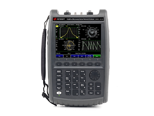
Keysight N9928A FieldFox Handheld Microwave Vector Network Analyzer, 26.5 GHz
- Configure as a full, two-port VNA, time-domain reflectometer, vector voltmeter, cable and antenna analyzer, and more
- Measure all four S-parameters simultaneously with a single connection and up to 95 dB of dynamic range
- Perform accurate testing with QuickCal, full two-port unknown thru Cal, and Thru, Reflect, Line (TRL) calibration in the field

Keysight N9952A FieldFox Handheld Microwave Analyzer | 50 GHz
- 50 GHz max frequency
- Carry industry’s first 50 GHz handheld µW analyzer: standard model includes cable and antenna analyzer
- Expand capabilities with optional VNA, spectrum analyzer, built-in power meter, vector voltmeter, and more

Keysight N9951A FieldFox Handheld Microwave Analyzer
- Frequency Range: 300 kHz – 44 GHz
- Dynamic Range: Up to 110 dB
- 2 Ports

Tektronix TTR506 Vector Network Analyzer
- Frequency range: 100 kHz – 6 GHz
- Dynamic range: Up to 122 dB
- 2 ports
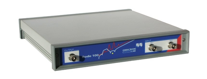
OMICRON Bode 100 Vector Network Analyzer 1 Hz - 40 MHz
- Swept S-parameters in the 50 system
- Reflection coefficient and return loss
- Insertion loss of filters

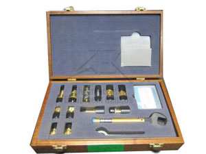
Keysight 85056A Standard Mechanical Calibration Kit 50 GHz
- DC to 50 GHz frequency range
- Calibration standards to perform full two-port calibration
- Torque wrenches for properly connecting standards
Keysight N5262AC15 Banded Millimeter Wave Calibration Kit
- Banded Millimeter Wave Calibration Kit
- Part of Keysight's series of wave network analysis solutions
- A frequency range of 50 to 75 GHz
Keysight N5262AC12 Banded Millimeter Wave Calibration Kit
- Part of Keysight's series of N5262A wave network analysis solutions
- Virginia Diodes Inc. calibration kit
- A frequency of 60 to 90 GHz
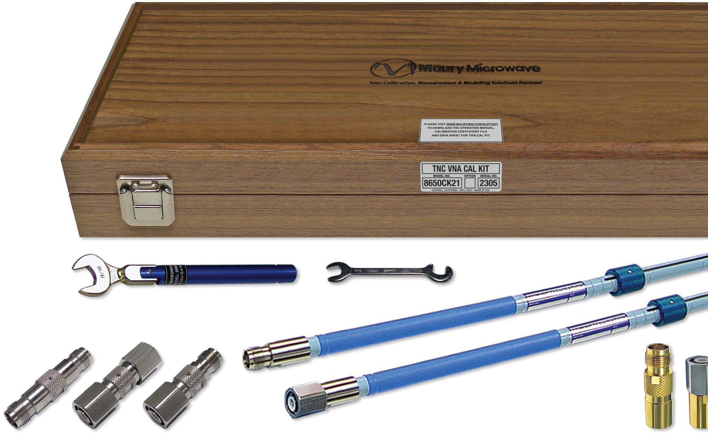
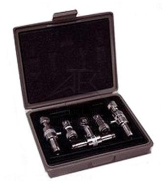
Maury Microwave 8650CK10 Calibration Kit
Keysight 85054D Mechanical Calibration Kit, DC - 18 GHz
- DC to 18 GHz frequency range
- Torque wrenches for properly connecting standards
- Calibration standards to perform full two-port calibration
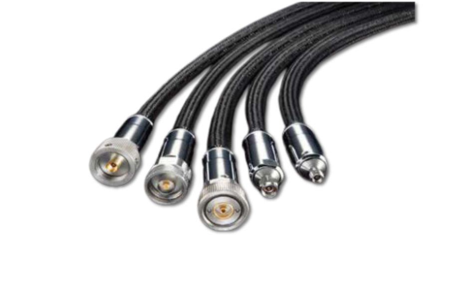
.png "Anritsu 15NNF50-1.5C Test Port Cables")
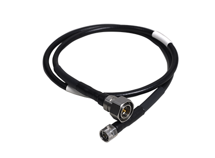
Anritsu 15NNF50-1.5C Test Port Cable
- Frequency: DC - 6.0GHz
- Connectors: Precision N(m), N(f)
- Length: 1.5m

Keysight 85052D Economy Mechanical Calibration Kit
- DC to 26.5 GHz frequency range
- Calibration standards to perform full two-port calibration
- Torque wrenches for properly connecting standards
Anritsu 15N43F50-1.5C Cable Assembly
- Phase and amplitude stable with flexure: longer calibration intervals, greater precision and accuracy
- Flexible: user friendly/easy to route
- Internally ruggedized: crush, torque and kink resistant

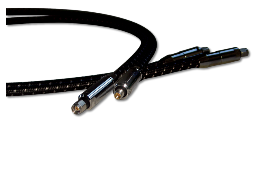
Times Microwave Systems CLS50-24F2RF-01.00M Clarity Armored VNA Cable
- DC - 50GHz
- 2.4mm(f) - 2.4mm(f)
- 1m (length)

Keysight 85032F Type-N Calibration Kit
- Frequency: DC - 9GHz
- Adapters: Type-N
- Impedance: 50Ω
.png "Times Microwave Systems SLSV50-24F2RF-01.00M")
Times Microwave Systems SLSV50-24F2RF-01.00M Silverline VNA Cable
- 50GHz
- 2.4mmF
- 1m (length)

MegaPhase VN18-32N1-36 VNA Test Port Cable
- DC - 18GHz
- 3.5mm(f) - N(m)
- 36in
MegaPhase VN18-31N1-36 VNA Test Port Cable
- DC - 18GHz
- 3.5mm(m) - N(m)
- 36in
.png "Times Microwave Systems SLSV40-KMKF-01.00M")
Times Microwave Systems SLSV40-KMKF-01.00M Silverline VNA Cable
- 40GHz
- 82dB/100ft (269dB/100m)
- 1m (length)
Keysight 85033A SMA Calibration Kit
- DC to 9 GHz frequency range
- Connector type to DUT is 7mm
Anritsu 3652A K Connector Calibration Kit
- 33KFKF50B Female-Female Adapter (2)
- 33KKF50B Male-Female Adapter (2)
- 33KK50B Male-Male Adapter (2)
Keysight 11570A, 50 OHM Accessory Kit

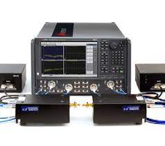
Rohde & Schwarz ZNB3000 Vector Network Analyzer Series
- 9 kHz – 20 GHz
- Up to 4 ports
- Dynamic Range: 125 – 155 dB

MegaPhase MP85131F-24 VNA Test Port Cable Set
- DC - 26.5GHz
- 3.5mm (m) to 3.5mm (f)
- 24in