

Ask us about
test equipment solutions for your industry
TWTA vs. SSPA: Comparing Traveling-Wave Tube and Solid-State RF Amplifiers

This comparison shows that Solid-State Power Amplifiers (SSPAs) produce a flatter gain response, while Traveling-Wave Tube Amplifiers (TWTAs) have a more pronounced midband gain peak. When choosing an amplifier, consider the amplifier’s capabilities and application requirements in addition to its architecture.
SSPAs are a practical starting point for many CW applications, while TWTAs are commonly used for applications requiring high microwave power, broad bandwidth, or high pulsed output.
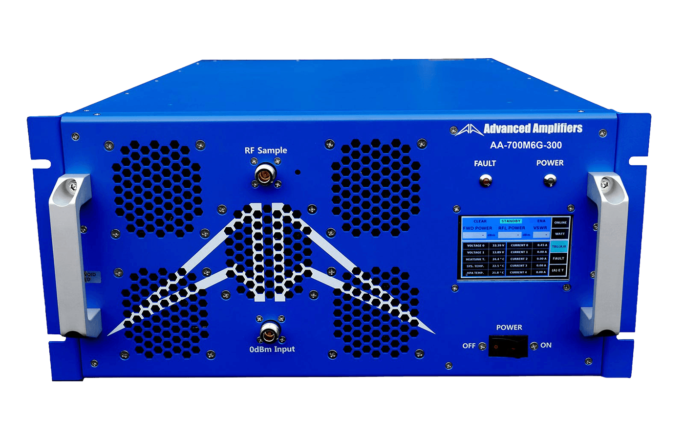
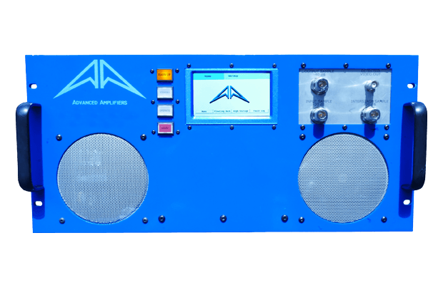
To define the differences between GaN solid-state RF and traveling-wave tube amplifiers, ATEC tested two equivalent RF Amplifiers (displayed below) made with the two different technologies, covering 2-8GHz and about 400W power output.
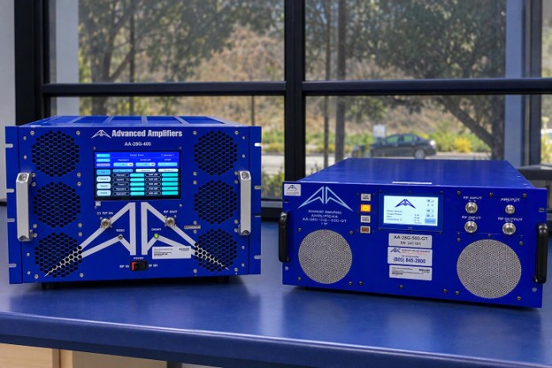
Figure 1. Advanced Amplifiers AA-28G-400 SSPA (left) and AA-28G-500-GT TWTA (right), at ATEC.
In this test, a Vector Network Analyzer (VNA) swept both amplifiers to illustrate a clear difference in the measured gain response between these two devices. This determined how much input power was necessary for each type of amplifier to produce the same output power.
Amplifier Gain Measurement Test Setup
Our Keysight E5063A VNA swept 2 - 8GHz with a -20dBm power level to check the amplifiers’ small-signal gain levels. Our Narda 27002SC-50 RF directional coupler supplied a 50dB forward power coupling port, which provided enough attenuation to sample the output signal on an S21 transmission measurement. We used a high-power termination with the coupler to complete the load. Using the two Times Microwave Systems SLU18-NMNF-01.00M RF low loss cables, we calibrated the coupler and cable’s through response in the test setup so we could insert both amplifiers and take our measurement.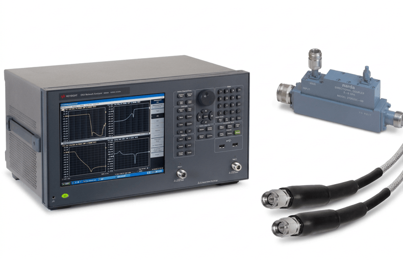
Figure 2. Collection of the products used for this test from: Keysight E5063A (left), Narda 27002SC-50 (upper right), and Times Microwave Systems SLU18-NMNF-01.00M (bottom right).
These measurements showed gain versus frequency at the -20dBm drive level. P1dB, or gain compression, was not characterized.
TWTA Gain Sweep
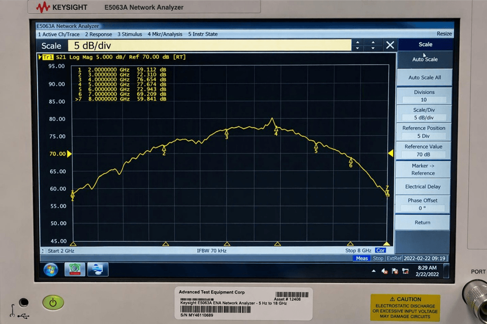
Figure 3. TWTA gain sweep from 2 to 8 GHz, displayed at 5 dB per division.
We provided a flat input drive between 2 – 8GHz and measured an 18.6dB gain variation which peaked in the middle of the band around 4.5GHz.
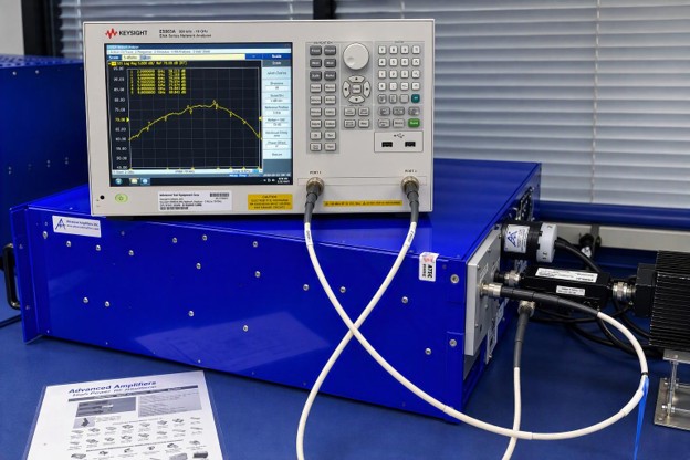
Figure 4. TWTA test setup with VNA, Coupler and High Power RF Termination.
This RF Sweep showed that the TWT Amplifier gain was not flat. The gain in the middle band of the TWTA was higher than any other point in the measurement.
While we hit our specified output power at mid band, at a -20dBm input, we did not hit our specified output. A higher drive is what allowed us to hit the 400W output power.
SSPA Gain Sweep
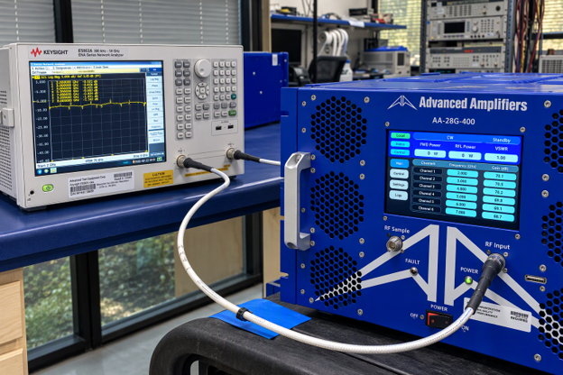
Figure 5. AA-28G-400 SSPA gain sweep displayed at 10 dB per division.
We scaled our solid-state power amplifier at 10dB/division and ended up with a flat response. To get a clearer idea of how linear this gain was, we then scaled our SSPA to 2dB/division.
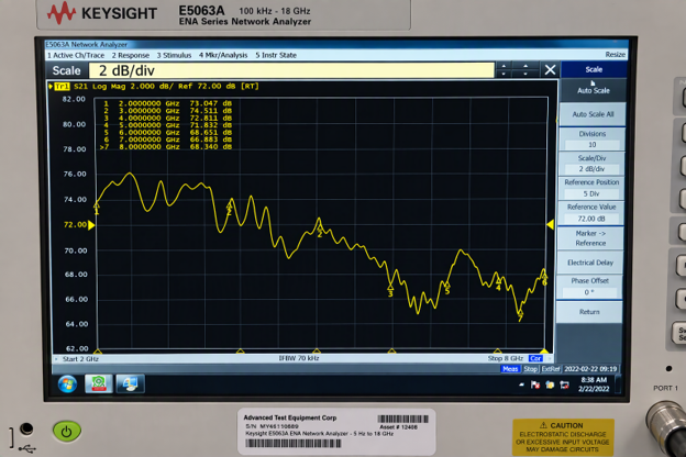
Figure 5. The same SSPA response at 2 dB per division, revealing gain falloff at higher frequencies.
When viewed at 2 dB/division, the sweep showed approximately 10 dB between the observed peaks and valleys; however, the measured gain variation was 6.2 dB. The SSPA maintained higher gain toward the band edges while providing the same output-power capability as the TWT.
Measured Gain Comparison
The table combines readings we gathered from the TWTA and SSPA sweeps. Values are rounded to 0.1 dB.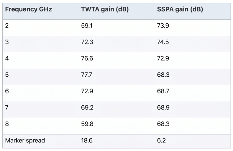
Figure 6. Comparison table for gain between TWTA and SSPA.
The two most important points to consider from this table are the significance of the falloff at 2 GHz and 8 GHz and the large 18.6 dB gain variation of the TWTA.
TWTA vs SSPA: Key Factors for Renting or Purchasing RF Amplifiers
When deciding whether to rent or purchase an RF amplifier, particularly when comparing Traveling-Wave Tube Amplifiers (TWTAs) and Solid-State Power Amplifiers (SSPAs), gain flatness is only part of the equation. Several critical operational and technical factors should also be considered:- Form Factor – TWTs are generally smaller and lighter than solid-state amplifiers, making them a viable solution depending on bandwidth and power requirements. Solid-state alternatives have different physical size and weight considerations relative to their power density.
- Load Mismatch & VSWR Handling – Whether an amplifier is used with an antenna for radiated testing or a device for conducted power-handling testing, VSWR and load mismatch must be considered. Most solid-state amplifiers incorporate some form of foldback protection, which reduces output power when reflected power exceeds a specified threshold, such as a 2:1 VSWR. With a TWT amplifier, a severe mismatch may instead trigger a protective shutdown, resulting in no RF output and an interruption to testing.
- Service Requirements – Solid state amplifiers’ service costs are a result of transistor failures, which are cheaper to fix or replace than the high voltage power supplies required by TWTs.
- Harmonics and Distortion – Both types of amplifiers can produce harmonics and distortion; however, TWTs can generate significant noise, which may be detrimental in communications applications.
- Signal Integrity – Every amplifier specifies its P1dB and gain compression. In this case, what matters isn’t the type of amplifier; it’s making sure the signal you need is not distorted or compressed. To ensure this, whatever amplifier you use should operate below its P1dB threshold.
- CW/Pulsed Output – While both solid-state and TWT amplifiers can provide continuous-wave (CW) or pulsed output, TWTAs inherently use grid-voltage switching, making them well suited for broadband, high-power pulsed applications.
Posted November 13, 2026
How ATEC Can Help You
ATEC services and tests SSPAs and TWTAs from a variety of brands, including Advanced Amplifiers, Amplifier Research, Empower, and Ophir RF. Reach out to ATEC today to learn more about our RF amplifier rental options.