MIL-STD-461G CE106 Standard Overview
MIL-STD-461G CE106 is a military test standard procedure that applies to the antenna ports of transmitters, receivers, and amplifiers over the frequency range of 10 kHz to 40 GHz. The requirement does not apply to equipment designed with antennas permanently mounted to the EUT. The transmit mode portion of MIL-STD-461G CE106 is not applicable within the bandwidth of the EUT transmitted signal or within ±5 percent of the fundamental frequency, whichever is larger. For Navy shipboard applications with peak transmitter power greater than 1 kW, the 5% frequency exclusion will be increased by an additional 0.1% of the fundamental frequency for each dB above 1 kW of peak power.
Frequency Exclusion = ± f * (0.05 + (0.001/dB) * (PtPk [dBm] – 60 [dBm]))
Depending on the operating frequency range of the EUT, the start frequency of the test is as follows:
The equipment will be tested to an upper-frequency limit based on the highest frequency generated or received by the EUT. For systems with the frequencies generated or received less than 1 GHz, the upper-frequency limit will be 20 times the highest frequency or 18 GHz, whichever is greater. For systems with frequencies generated or received greater than or equal to 1 GHz, the upper-frequency limit will be 10 times the highest frequency or 40 GHz, whichever is less. For equipment using waveguide, the requirement does not apply below eight-tenths of the waveguide's cutoff frequency. RE103 may be used as an alternative for MIL-STD-461G CE106 for testing transmitters with their operational antennas.
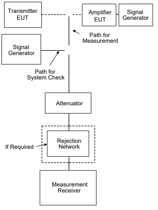
FIGURE CE106-1. Setup for low power transmitters and amplifiers.
_20.png "Figure-CE106-1-(1).PNG")
FIGURE CE106-2. Setup for high power transmitters and amplifiers.
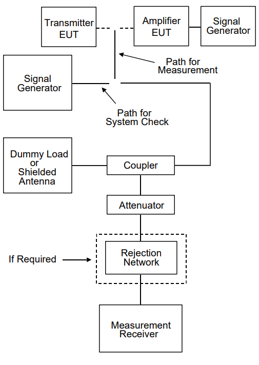
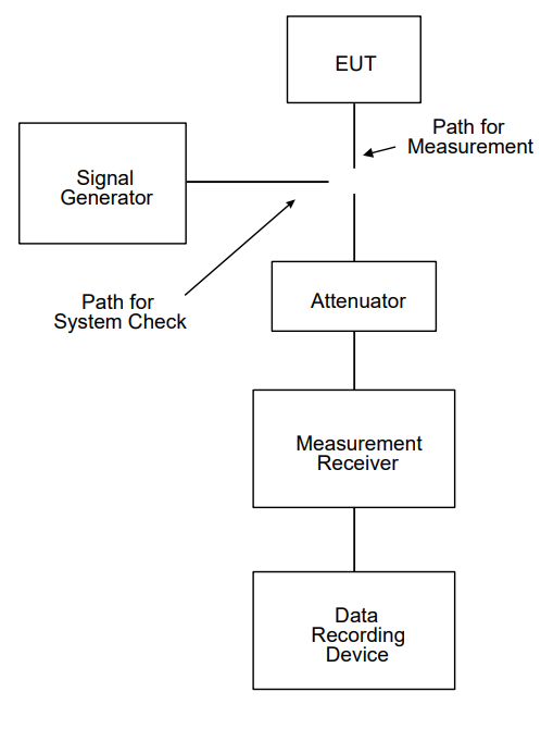
FIGURE CE106-3. Setup for receivers and stand-by mode for transmitters and amplifiers.
Download Standard
Frequency Exclusion = ± f * (0.05 + (0.001/dB) * (PtPk [dBm] – 60 [dBm]))
Depending on the operating frequency range of the EUT, the start frequency of the test is as follows:
| EUT Operating Frequency Range | Start Frequency of Test |
|---|---|
| 10 kHz to 3 MHz | 10 kHz |
| 3 MHz to 300 MHz | 100 kHz |
| 300 MHz to 3 GHz | 1 MHz |
| 3 GHz to 40 GHz | 10 MHz |
The equipment will be tested to an upper-frequency limit based on the highest frequency generated or received by the EUT. For systems with the frequencies generated or received less than 1 GHz, the upper-frequency limit will be 20 times the highest frequency or 18 GHz, whichever is greater. For systems with frequencies generated or received greater than or equal to 1 GHz, the upper-frequency limit will be 10 times the highest frequency or 40 GHz, whichever is less. For equipment using waveguide, the requirement does not apply below eight-tenths of the waveguide's cutoff frequency. RE103 may be used as an alternative for MIL-STD-461G CE106 for testing transmitters with their operational antennas.
Test Equipment
- Measurement receiver
- Attenuators, 50 ohm
- Rejection networks
- Directional couplers
- Dummy loads, 50 ohm
- Signal generators
- For amplifier testing, a signal generator is required to drive the amplifier that provides the modulation used in the intended application and that has spurious and harmonic outputs that are at least 6 dB below the applicable limit.
- Data recording device
Procedures
The test procedure shall be as follows:- a. Turn on the measurement equipment and allow sufficient time for stabilization.
- b. Measurement system integrity check.
- (1) Apply a known calibrated signal level from the signal generator through the system check path at a mid-band fundamental frequency (fo).
- (2) Scan the measurement receiver in the same manner as a normal data scan. Verify the measurement receiver detects a level within ±3 dB of the expected signal.
- (3) If readings are obtained which deviate by more than ±3 dB, locate the source of the error and correct the deficiency before proceeding with the test.
- (4) Repeat 5.6.3.4.1b(1) through 5.6.3.4.1b(3) at the endpoints of the frequency range of the test.
- c. EUT testing.
- (1) Turn on the EUT and allow sufficient time for stabilization.
- (2) For transmitters, tune the EUT to the desired test frequency and apply the appropriate modulation for the EUT as indicated in the equipment specification. Downloaded from www.atecorp.com MIL-STD-461G 42 CE106 For amplifiers, apply an input signal to the EUT that has the appropriate frequency, power level, and modulation as indicated in the equipment specification. For transmitters and amplifiers for which these parameters vary, test parameters shall be chosen such that the worst-case emissions spectrum will result.
- (3) Use the measurement path to complete the rest of this procedure.
- (4) Tune the test equipment to the operating frequency (fo) of the EUT and adjust for maximum indication.
- (5) Record the power level of the fundamental frequency (fo) and the measurement receiver bandwidth.
- (6) Insert the fundamental frequency rejection network, when applicable.
- (7) Scan the frequency range of interest and record the level of all harmonics and spurious emissions. Add all correction factors for cable loss, attenuators and rejection networks. Maintain the same measurement receiver bandwidth used to measure the power level of the fundamental frequency (fo) in 5.6.3.4.1c(5).
- (8) Verify spurious outputs are from the EUT and not spurious responses of the measurement system.
- (9) Repeat 5.6.3.4.1c(2) through 5.6.3.4.1c(8) for other frequencies as required by 4.3.9.1 and 4.3.9.2.
- (10) Determine measurement path losses at each spurious frequency as follows:
- (a) Replace the EUT with a signal generator.
- (b) Retain all couplers and rejection networks in the measurement path.
- (c) Determine the losses through the measurement path. The value of attenuators may be reduced to facilitate the end-to-end check with a low-level signal generator.
Test Setup
It is not necessary to maintain the basic test setup for the EUT as shown and described in Figures 2 through 5 and 4.3.8. The test setup shall be as follows:- a. Measurement system integrity check. Configure the test setup for the signal generator path shown on Figures CE106-1 through CE106-3 as applicable. The choice of Figure CE106-1 or CE106-2 is dependent upon the capability of the measuring equipment to handle the transmitter power.
- b. EUT testing. Configure the test setup for the EUT path shown on Figures CE106-1 through CE106-3 as applicable. The choice of Figure CE106-1 or CE106-2 is dependent upon the capability of the measuring equipment to handle the transmitter power.
FIGURE CE106-1. Setup for low power transmitters and amplifiers.
FIGURE CE106-2. Setup for high power transmitters and amplifiers.
FIGURE CE106-3. Setup for receivers and stand-by mode for transmitters and amplifiers.
Download Standard