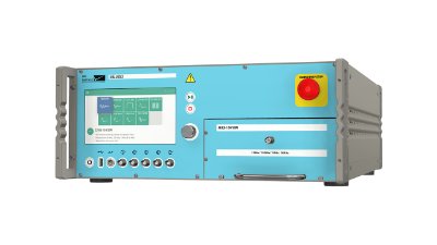
MIL-STD-461G CS116 Standard Overview
MIL-STD-461G CS116 is used to verify the ability of the EUT to withstand damped sinusoidal transients coupled onto EUT associated cables and power leads. MIL-STD-461G CS116 applies to all interconnecting cables, including power cables, and individual high side power leads. Power returns and neutrals need not be tested individually. For submarine applications, MIL-STD-461G CS116 applies only to cables and leads that exit the pressure hull.
FIGURE CS116-1. Typical CS116 damped sinusoidal waveform.
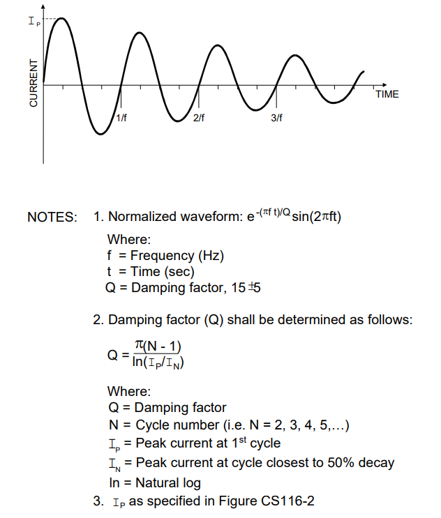
FIGURE CS116-2. CS116 limit for all applications
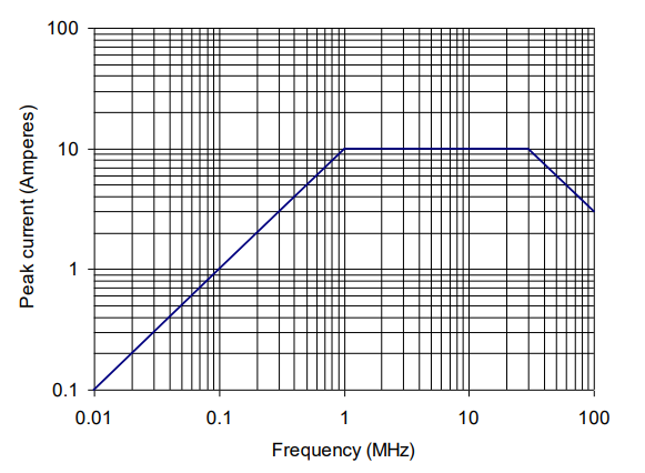
FIGURE CS116-3. Typical test setup for calibration of test waveform.
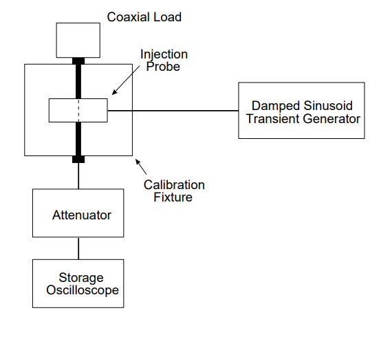
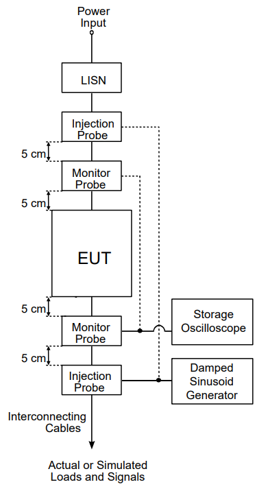
FIGURE CS116-4. Typical set up for bulk cable injection of damped sinusoidal transients.
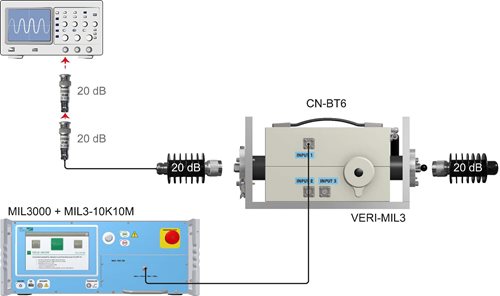
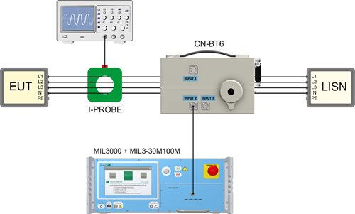
CS 116 test setup (10 kHz –10 MHz):
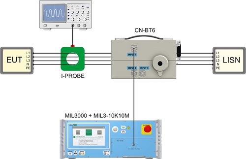
CS 116 calibration setup (30 MHz –100 MHz):
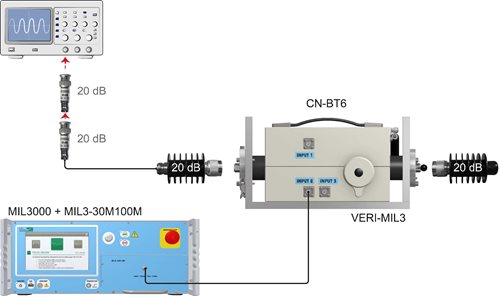
Test Equipment
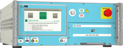
- Damped sinusoid transient generator, ≤ 100 ohm output impedance
- Current injection probe
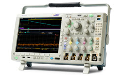
- Oscilloscope, 50 ohm input impedance
- Calibration fixture: Coaxial transmission line with 50 ohm characteristic impedance, coaxial connections on both ends, and space for an injection probe around the center conductor
- Current probe
- Waveform recording device
- Attenuators, 50 ohm
- Measurement receivers
- Coaxial loads, 50 ohm
- LISNs
Procedures
The test procedures shall be as follows:- a. Turn on the measurement equipment and allow sufficient time for stabilization.
- b. Calibration. Perform the following procedures using the calibration setup for waveform verification.
- (1) Set the frequency of the damped sine generator at 10 kHz.
- (2) Adjust the amplitude of the signal from the damped sine generator to the level specified in the requirement.
- (3) Record the damped sine generator settings.
- (4) Verify and record that the waveform complies with the requirements. Calculate and record the damping factor (Q).
- (5) Repeat 5.14.3.4b(2) through 5.14.3.4b(4) for each frequency specified in the requirement.
- c. EUT testing. Perform the following procedures, using the EUT test setup on each cable bundle interfacing with each connector on the EUT including complete power cables. Also, perform tests on each individual high side power lead (individual power returns and neutrals are not required to be tested). For delta configured power leads, test each power lead separately in addition to bulk cable.
- (1) Turn on the EUT and measurement equipment to allow sufficient time for stabilization.
- (2) Set the damped sine generator to a test frequency.
- (3) Apply the calibrated test signals to each cable or power lead of the EUT sequentially. Reduce the signal, if necessary, to produce the required current. For shielded cables or low impedance circuits, it may be preferable to increase the signal gradually to limit the current. Record the peak current obtained.
- (4) Monitor the EUT for degradation of performance.
- (5) If susceptibility is noted, determine the threshold level in accordance with 4.3.10.4.3.
- (6) Repeat 5.14.3.4c(2) through 5.14.3.4c(5) for each test frequency as specified in the requirement.
TEST Setup
- The test setup shall be as follows:
- a. Maintain a basic test setup for the EUT as shown and described in Figures 2 through 5 and 4.3.8.
- b. Calibration. Configure the test equipment in accordance with Figure CS116-3 for verification of the waveform.
- c. EUT testing:
- (1) Configure the test equipment as shown in Figure CS116-4.
- (2) To minimize errors, maintain the same signal circuit that was used for calibration between the attenuator at the calibration fixture (oscilloscope, coaxial cables, bulkhead connectors, additional attenuators, etc.) and connect the circuit to the monitor probe. Additional attenuation may be used, if necessary.
- (3) Place the injection and monitor probes around a cable bundle interfacing an EUT connector.
- (4) Locate the monitor probe 5 cm from the connector. If the overall length of the connector, backshell or backshell extension exceeds 5 cm, position the monitor probe as close to the connector's backshell or backshell extension as possible.
- (5) Position the injection probe 5 cm from the monitor probe.
FIGURE CS116-1. Typical CS116 damped sinusoidal waveform.
FIGURE CS116-2. CS116 limit for all applications
FIGURE CS116-3. Typical test setup for calibration of test waveform.
FIGURE CS116-4. Typical set up for bulk cable injection of damped sinusoidal transients.
Calibration
CS 116 calibration setup (10 kHz –10 MHz):
CS 116 test setup (10 kHz –10 MHz):
CS 116 calibration setup (30 MHz –100 MHz):
CS 116 test setup (30 MHz –100 MHz):